One of the challenges for designers of LED lamps is to create a lighting system that produces constant light output, without noticeable flickering. In systems that use a single-stage LED driver, flicker-free lighting can be hard to achieve, since random distortions in the line voltage can make the LED current unstable, and that can produce flickering. The feedback response circuit is often the underlying cause of the problem, since it may not be reacting quickly enough to the distortions.
To address this problem, we designed a 7.8 W LED system and experimented with the power factor correction (PFC) control circuit. We found that a combination of two things — using an internally generated sine reference and discontinuous conduction mode (DCM) operation — can improve performance, reduce component count, and eliminate flicker.
Internal Generation of the Digital Sinusoidal Reference
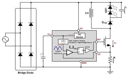
In most designs that use current-mode operation to control PFC, the sine reference is obtained by using a resistive divider to sense the input voltage. An internally generated sine reference, produced using digital mapping, makes the LED current of the buck-boost topology more stable. Internal generation of the sine reference also makes it possible to eliminate the resistive divider, for lower component count and a more compact design. Figure 1 gives the block diagram of the circuit.
 |
|
Figure 1. LED Driver Configuration |
The supply voltage (Vcc) is supplied by a high-voltage (HV) device built into the controller. The input voltage zero crossing is detected through the Vcc and HV blocks, so the internal sine reference is synchronized with the zero-crossing signal. The output signal from the on-chip digital-to-analog converter (DAC) produces a digital sinusoidal reference using the internally mapped sine information and the synchronized the zero-crossing signal. When the Vcc voltage is less than 15.5 V, the zero-crossing detector (ZCD) voltage is low and the DAC and internal clock automatically provide a digital reference signal with a 32-bit digital step.
CRM Versus DCM Operation
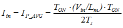
In converters that use a boost topology, input current is configured by the inductor current. This optimizes PFC in critical-conduction mode (CRM) operation, since there is a constant on-time with variable off-time. With the buck-boost topology, on the other hand, input current is proportional to switch current. As a result, PFC is degraded in CRM operation, and the line peak voltage is flatter. Input current is determined by the inductor current associated with MOSFET turn-on. Equation 1 shows how to calculate the input current in the buck-boost converter.
 |
|
(Equation 1) |
Based on Equation 1, input current becomes proportional to input voltage by controlling the constant turn-on time and constant switching period in the buck-boost converter. This means that the best method is discontinuous conduction mode (DCM) operation with fixed turn-on time.
Constant-Current Line Regulation
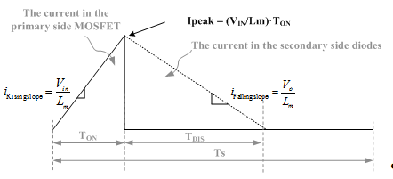
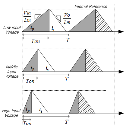
As described above, to improve LED current fluctuation and line-voltage distortion, our design uses DCM operation and the fixed internal sine reference in a buck-boost converter. This approach does an excellent job of regulating the LED current, without visible flicker, even if there is a line voltage transient between 90Vac and 265Vac. Figure 2 shows the current slope for the inductor current.
 |
|
Figure 2. Current Slope for Inductor Current |
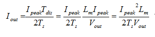
Based on the results of Figure 2, the output current can be calculated using Equation 2.
 |
|
(Equation 2) |
In Equation 2, since the fixed sine Ipeak is controlled by an internal reference, the output current is not a function of the input voltage. Figure 3 shows the constant-current line regulation.
 |
|
Figure 3. Constant-Current Line Regulation |
When the input voltage is varied, LED current is constantly regulated by the fixed Ipeak and the falling slope of the fixed inductor current.
Constant-Power Load Regulation
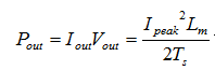
Using the proposed LED driving method, output current is not constantly regulated when output voltage changes. Equation 3, which is derived from Equation 2, shows the output power calculation.
 |
|
(Equation 3) |
Because Ipeak and Ts are fixed by the controller, the output current is reduced and the output power is consistently regulated as the output voltage increases.
Regulation: Line Versus Load
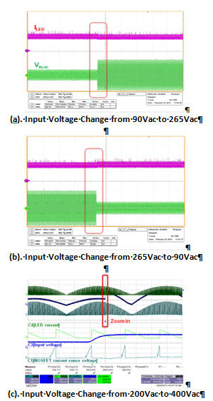
In general, line regulation is used to regulate output current in response to variations in input voltage. Load regulation is used to maintain output power independent of changes in the LED forward voltage. As forward voltage goes down in response to system temperature or LED derating, constant-current load regulation is used to reduce LED power with a luminous decrease. Figure 4 shows distortion in the line voltage caused by changes in the input voltage from (a) 90 Vac to 265 Vac, (b) 265 Vac to 90 Vac, and (c) 200 Vac to 400 Vac.
 |
|
Figure 4. Line Voltage Distortion |
Conclusion
The combination of a buck-boost LED driver that uses a fixed sine reference in DAC and DCM modes, with fixed frequency, can help reduce flicker. The internally generated sine reference greatly reduces LED current when there are random changes in line voltage. Also, the design delivers more consistent brightness with constant power load regulation, because the current-mode control uses temperature or LED derating to compensate for the LED forward voltage drop.