MR11/16 LED Lamp LED Driver Design
In Part II of our series on Solutions for Today’s Low Power LED Lighting Trends we listed the many regulatory and industry standards that designers need to account for in order to understand the design constraints of any given project for reducing power losses, power factor correction and low THD in the LED driver. In addition to the regulations and standards discussed, there are a number of other factors that need to be considered that can impact design. These include:
-
Development cycle-time and design complexity
-
Efficiency and efficacy
-
Operating temperature
-
No flicker & No flashing
-
Constant current output tolerance
-
Vendor selection and consolidation
-
Cost, Reliability and lifetime of the driver
-
Protections – OVP, OCP, OTP, short-circuit LED, open-circuit LED
-
Limited printed circuit board (PCB) space or volume (height) constraints
-
Identifying a power topology that meets input and output voltage-current parameters, thermal design, safety regulations, and protection needs
-
Dimming and dimming range (phase cut dimmer requirement, dimming ratio, inrush current limit, damping circuit, bleeder, etc.)
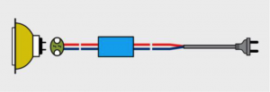
MR11 & MR16 (MR stands for the ‘multifaceted reflector’ housing format) bulbs are typically halogen lamps and common types are 20W, 35W, and 50W ratings. The typical design of existing halogen designs is shown in Figure 1.
 |
|
Fig. 1. Existed Conventional Halogen Infra structure (Source: Fairchild Semiconductor) |
The input voltage can be DC 12V or 24V or plugged directly into a 120V or 230V AC mains supply. The 12V or 24V can also be derived from a simple transformer that takes the mains AC voltage and outputs a 12V/24V AC input to the light socket. The LED replacement needs to be controlled as a constant-current source. A 4W led MR lamp is the equivalent to a 20W halogen lamp design. Dimming is a feature found on some models, with the trend toward dimming increasing in availability.
MR11/16 Lamp LED Driver Design Challenges
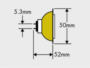
The top challenges for the MR11/16 design are the lack of standards on the lamp fixture and the bulb shape, the power factor, total harmonic distortion requirement (Energy Star for LED luminaries ≥0.9, integral lamp ≥0.7 for >5W), and low system power efficiency. The small space for the LED driver can be appreciated by considering the Fig. 2 lamp dimensions, which must include the driver.
 |
|
Fig. 2. MR Lamp Dimensions (Source: Fairchild Semiconductor) |
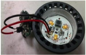
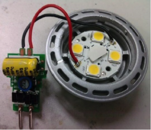
There are two types of printed circuit board form factors. One shape, shown in Fig. 3, is round to adapt with the LED module back side. The round diameter should be smaller than 30 mm with taller components located within 5 mm from the center connector. The other, shown in Fig. 4, is vertical; it needs to be smaller than 30 x 20 mm.
 |
|
Fig. 3. MR Lamp Round Type PCB Design (Source: Fairchild Semiconductor) |
 |
|
Fig. 4. MR Lamp Vertical Type PCB Deign (Source: Fairchild Semiconductor) |
MR11/16 Lamp Fairchild Solutions
A proper LED driver topology can result in the best cost solution. If the input voltage is 12V or 24V DC, the LED driver DC-DC topology choice is either a boost or buck topology. If the LED total string forward voltage is higher than the rectified input voltage, use a boost topology; otherwise, use the buck topology. The DC-DC power stage efficiency is high; it can generally reach up to 90%. However, the ballast transformer efficiency is poor. The ballast transformer is not a switched-mode power supply (SMPS), just a transformer converting 110V/220Vac to 12V/24Vac. Although the DC-DC power stage efficiency is high, the total system efficiency for the AC-DC transformer + DC-DC topology is low.
The poor system efficiency and PFC and THD requirement need to be solved for the MR LED lamp driver to fit within a limited small PCB space. The current solution using an AC-DC transformer plus DC-DC topology is the current installed infrastructure: a Halogen socket and ballast transformer. It results in saving on installation investment cost, but electrical efficiency is sacrificed. This infrastructure trend is to be replaced by a more efficient configuration. Manufacturers are starting to release an AC-DC MR lamp into the market place.
The AC-DC MR lamp integrates the LED driver into the lamp case without the need for the ballast transformer. It is possible to achieve over 80% total power efficiency in this configuration. In general, it is not easy to build an AC-DC LED driver board into the small bulb case while also meeting PF and THD requirements in the application. It is also preferred not to use an electrolytic capacitor whose life time is less than the other semiconductor components or passive electric components like the resistors, ceramic capacitors, and inductors. The AC-DC MR-type LED lamp design is a new design challenge.
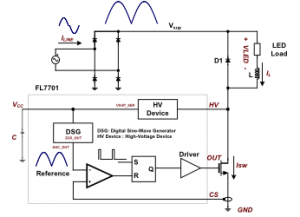
Fairchild suggests a new LED driver device to solve the AC-DC issues; the FL7701, shown in Fig. 5.
 |
|
Fig. 5. Smart Non-Isolated PFC Buck LED Driver Solution (Source: Fairchild Semiconductor) |
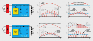
It is a “smart” non-isolated PFC buck LED driver solution. With direct AC line input voltages, it is possible to achieve a small PCB outline adaptable to the MR lamp case. This LED driver device eliminates the need for all electrolytic capacitors typically used for the input, output, and IC Vcc voltages. Eliminating the electrolytic capacitors lengthens the product life and reduces the PCB space, while resulting in a low BOM cost. Using only a few external components, it meets PF and THD requirements, while achieving efficiency over 80%. The buck topology also has the advantage of constant output current (reduced ripple current) versus a boost design, since the inductor is placed in series with the output, i.e. the buck topology looks like a constant current source to the LED load. The boost topology has discontinuous output current unless an output capacitor is used to filter the ripple current. A waveform comparison is shown in Fig 6.
 |
|
Fig. 6 Buck versus Boost Topology Comparison |
Want to design a Buck LED Driver with optimum RCD snubber in minutes? Check out our Power Supply WebDesigner tool at: https://info.fairchildsemi.com/FY1501–Bog–AEP3680–1–Design-Tools.html
Want to read more about Fairchild solutions for today’s LED lighting applications? – Download our application guide: https://info.fairchildsemi.com/FY1501–Bog–AEP3680–2–LED-Lighting-Solutions-Guide.html
Please visit our LED resource page to learn about Fairchild’s LED lighting solutions. In Part IV we’ll blog about A19, E14/17, E26/27 Bulb Lamp LED Driver Design.
(Authors: James Lee, Brian Johnson and Richard Chung of Fairchild Semiconductors)


